
Data Center Power Distribution Fuses: From Utility Entrance to Server Rack
Data Center Power Distribution Fuses: From Utility Entrance to Server Rack
A modern data center’s electrical system carries power from the utility service entrance through multiple transformation and protection stages before reaching individual server racks. Each stage has different fuse requirements driven by voltage level, available fault current, continuous current, and the criticality of uptime. A single coordination failure can cascade into downtime costing thousands of dollars per minute.
This guide walks through every stage of data center power distribution, identifying the appropriate fuse class, rating, and AIC for each location.
Data Center Power Chain Overview
A typical Tier III or Tier IV data center has the following power architecture:
“ Utility Feed (13.8 kV or 480 V) ↓ Main Switchgear / Service Entrance ↓ UPS (Uninterruptible Power Supply) ↓ PDU (Power Distribution Unit) ↓ Busway or RPP (Remote Power Panel) ↓ Server Rack PDUs ↓ IT Equipment (servers, switches, storage) “
Some designs add STS (Static Transfer Switch) between two independent utility feeds for redundancy, or battery cabinets for additional ride-through time beyond the UPS.
Stage 1: Utility Service Entrance
The utility feed at the service entrance is typically 13.8 kV three-phase (medium voltage) or 480 V three-phase (low voltage).
Medium voltage (13.8 kV):
- Use medium voltage fuses (Bussmann 5HLE, 8HLE, or 15HLE series)
- Current-limiting, rated 15.5 kV, with AIC up to 63 kA
- Sized at 125-150% of transformer full-load current
- Often combined with a load-break switch for isolation
Low voltage (480 V):
- Use Class L fuses (Bussmann KRP-C, KTU, or LOW-PEAK series) for the main disconnect
- Class L is rated up to 6000 A and 200 kA AIC
- Time-delay construction allows transformer inrush without nuisance tripping
For a 2500 kVA transformer at 480 V with 5.75% impedance:
- Full-load current: 3008 A
- Fuse size: 3500-4000 A Class L
- Available fault current at transformer secondary: approximately 52,000 A
- Required AIC: 65 kA minimum, 200 kA preferred
Stage 2: UPS Input and Bypass
The UPS protects downstream loads from utility disturbances. UPS inputs typically have two protection paths:
- Main input: From utility, feeds the rectifier
- Bypass input: From utility (separate path or same), feeds the bypass switch
For a 500 kVA UPS at 480 V:
- Full-load current: 600 A
- Main input fuse: 800 A Class J (LPJ) or 700 A Class L
- Bypass fuse: Same as main input
The UPS rectifier is sensitive to overcurrent and has its own internal protection, but the upstream fuse must isolate the UPS from external faults.
Stage 3: UPS Battery Protection
The UPS battery (typically VRLA or lithium-ion) is a separate protection concern. Battery strings can deliver very high fault currents — a fully charged 500 kVA UPS battery string can deliver 10-20 kA through a low-impedance short.
Battery fuses must be:
- DC-rated with verified DC interrupting rating
- High AIC to handle battery short-circuit current
- Fast-acting to disconnect the battery before thermal runaway
Common choices:
- Bussmann 170M series (high-speed square-body fuses, 1000 V DC, up to 2000 A)
- Bussmann FWP series (700-1000 V DC, 100-1000 A)
For a 500 kVA UPS battery string operating at 480 V DC:
- Continuous current: 1000 A
- Fuse size: 1200-1400 A
- Required AIC: 50 kA at 480 V DC minimum
Stage 4: UPS Output to PDU
The UPS output is typically 480 V three-phase. The output feeds a PDU (Power Distribution Unit), which transforms the voltage to 208 V or 120 V for IT loads.
For a 500 kVA UPS output:
- Full-load current: 600 A at 480 V
- Output fuse: 800 A Class J (LPJ) or 700 A Class L
Some data centers use busway instead of cables for the UPS-to-PDU connection. Busways have integrated fuse disconnects or breaker tap-offs at each PDU location.
Stage 5: PDU Output
The PDU transforms 480 V to 208/120 V for server racks. The PDU secondary protection is typically:
- Main PDU breaker: 800-1200 A molded case circuit breaker
- Sub-feed breakers: 100-400 A for individual RPPs or busway feeds
- Fuses: Less common at this stage, but some designs use Class J fuses for higher AIC in compact packages
For a 300 kVA PDU at 208 V:
- Full-load current: 833 A
- Main fuse: 1000 A Class L
- Sub-feed fuses: 100-400 A Class J or breakers
Stage 6: Busway and Remote Power Panels
Modern data centers increasingly use busway (overhead power distribution) instead of cables for flexibility and easier capacity changes. Busways have tap-off units at each rack row, allowing power to be added or rerouted without shutting down.
Busway tap-off protection:
- Class J fuses (LPJ series) for 100-600 A tap-offs
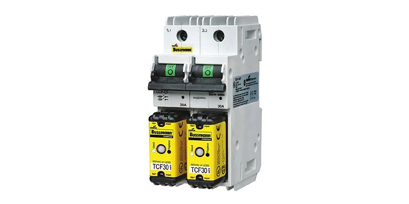
- Finger-safe CUBEFuse holders (TCF series) for 1-100 A tap-offs
- Optional metering at each tap-off for load monitoring
Stage 7: Rack-Level PDUs
The final stage is the rack PDU (rPDU), which distributes 208 V or 120 V to individual IT devices. rPDUs have many outlets (24-48 C13/C19 outlets per unit) and may include per-outlet metering, switching, and monitoring.
Rack-level protection typically uses:
- Miniature circuit breakers in the rPDU
- Or Class CC fuses (LP-CC series) for high-AIC protection in compact packages
For a 30 A rPDU at 208 V:
- Continuous current: 24 A at full load
- Branch fuse: 30 A Class CC (LP-CC), rated 600 V AC, 200 kA AIC
- Per-outlet protection: Optional, often not provided
Selective Coordination for Data Centers
Selective coordination is mandatory for data center power systems per NEC 240.12 and many local codes. Every fault must be cleared by the device closest to the fault, without upstream devices opening.
For fuses in series, coordination is straightforward:
Upstream fuse pre-arcing I2t ≥ Downstream fuse total clearing I2t × 1.5
The 1.5× safety margin accounts for:
- Fuse element aging over time
- Ambient temperature variations
- Manufacturing tolerances
For example, a 4000 A Class L main fuse has pre-arcing I2t of approximately 12,000,000 A2s. A downstream 800 A LPJ has total clearing I2t of approximately 1,500,000 A2s at the available fault current. The ratio is 8:1 — well above the 1.5× requirement.
High AIC Considerations
Data center fault currents can exceed 100 kA at the service entrance. Standard 10 kAIC circuit breakers are completely inadequate. Specify:
- 65 kAIC minimum for sub-feed and distribution panels
- 100 kAIC preferred for downstream of large transformers
- 200 kAIC for any device close to the service entrance
Class L, Class J, Class RK1, and Class CF fuses all provide 200-300 kA AIC and are appropriate for data center applications.
Uptime Implications of Fuse Selection
Fuses have a fundamental reliability advantage over circuit breakers: no mechanical parts to fail, no trip unit to misadjust, and a much longer service life. For data center applications where uptime is paramount, specifying fuses over breakers at critical protection points can reduce the risk of nuisance trips and improve mean time between failures (MTBF).
The trade-off is that fuses must be replaced after they operate, while breakers can be reset. For non-critical feeders, breakers offer operational convenience. For critical feeders where a coordination failure would cause downtime, fuses provide superior protection.
Common Data Center Fuse Specs
For a 2 MW Tier III data center:
Frequently Asked Questions
Are circuit breakers or fuses better for data centers? Both are used, but fuses offer higher AIC in smaller packages, longer life, and no mechanical failure modes. Breakers offer reset convenience. Critical feeders often use fuses; non-critical feeders use breakers.
What is the typical data center service voltage? Medium voltage (13.8 kV) utility feed, transformed to 480 V three-phase for distribution. Some facilities use 415 V (Europe) or 400 V (Asia).
How do I size fuses for UPS batteries? Calculate the maximum battery short-circuit current from the battery manufacturer’s published data. Add 25% margin. Specify DC-rated fuses with AIC greater than the calculated short-circuit current.
Do I need DC-rated fuses for UPS battery cabinets? Yes. Standard AC fuses will not reliably interrupt DC fault current. Use only fuses with explicit DC voltage and DC AIC ratings.
Where to Source Data Center Fuses
FuseStock stocks the complete Bussmann fuse line for data center power distribution — Class L, Class J, Class CF, Class CC, and DC-rated semiconductor fuses. Submit a request for our data center fuse selection worksheet to streamline your specification.