
EV Charging Station Fuse Selection: DC Fast Charger Protection Guide
EV Charging Station Fuse Selection: DC Fast Charger Protection Guide
DC fast charging stations for electric vehicles present unique protection challenges: high DC voltages (400 V to 1000 V depending on EV battery architecture), high continuous currents (up to 500 A per charging cable), and bidirectional power flow in some V2G configurations. Generic AC fuse rules do not apply — DC-rated fuses with verified DC interrupting ratings are essential.
This guide covers the protection architecture for CCS (Combined Charging System), CHAdeMO, and Tesla Supercharger stations, including the specific fuse requirements at each stage of the power path.
EV Charging Power Levels
EV charging is broadly classified by power level:
Level 1 and Level 2 use AC fuses rated 250 V AC or 600 V AC. Level 3 and Level 4 require DC-rated fuses because the rectified output cannot rely on the natural zero-crossing of AC for arc extinction.
DC Fast Charger Architecture
A typical CCS-2 / CCS-1 DC fast charger consists of:
- AC input section: Utility feed, disconnect, surge protection, AC fuses for the rectifier input
- Power factor correction (PFC): Boost converter stage that shapes the input current
- DC-DC converter: Isolated high-frequency converter that steps down (or up) the DC bus voltage
- DC output section: Output filter, output contactor, DC fuses, current sensor, and the CCS connector cable
- Controller and communication: PLC-based communication per ISO 15118 (CCS) or CHAdeMO protocol
Each of these sections has specific fuse requirements.
AC Input Protection
The AC input side of a DC fast charger typically operates at 480 V three-phase. Standard AC fuses apply:
- Main disconnect: Class J (LPJ) or Class L fuses rated 600 V AC, with AIC of 200 kA or 300 kA
- Branch circuit to rectifier: Class J fuses sized to 125-150% of rectifier input current
- Surge protection: Type 1 or Type 2 SPD at the service entrance
For a 150 kW charger drawing approximately 220 A at 480 V three-phase, a 300 A Class J disconnect is typical. The 300 kA AIC of LPJ fuses covers the available fault current from any commercial utility service.
DC Bus Protection — The Critical Section
The DC bus of a fast charger operates at 400 V (for 400 V battery EVs) up to 1000 V (for 800 V architecture vehicles like Porsche Taycan, Hyundai E-GMP, Lucid Air, Tesla Cybertruck). The DC bus fuses must:
- Be DC-rated with published DC voltage and DC interrupting rating
- Have high AIC because DC fault currents from the battery can be very high (batteries can deliver 10-50 kA through a low-impedance short)
- Have low I2t to protect the semiconductor switching devices in the converter
- Operate quickly to prevent thermal runaway in the battery during a fault
For DC bus fusing in a fast charger, semiconductor fuses are often specified:
- Bussmann FWH series (500 V AC / 500 V DC, 50 kA AIC at 500 V DC)
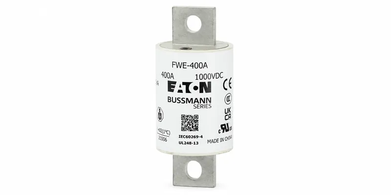
- Bussmann FWJ series (1000 V DC, 50-100 kA AIC at 1000 V DC)
- Bussmann FWP series (700-1000 V DC for PV and energy storage)
These fuses have very low I2t values and are designed specifically for semiconductor protection in DC circuits.
DC Output Cable Protection
The charging cable itself carries the full charging current (typically 125 A to 500 A) at the battery voltage. Protection must address:
- Overcurrent: A sustained overcurrent (e.g., failed current sensor) can overheat the cable insulation
- Short circuit: A cable fault (mechanical damage, water ingress) can deliver thousands of amps from the battery
- Reverse current: If the charger has bidirectional V2G capability, current can flow from the EV back into the charger
For a typical 350 kW charger with 500 A continuous output current at 800 V:
- Output fuse: 600-800 A semiconductor fuse rated 1000 V DC, mounted as close to the connector as practical
- Contactor: DC-rated contactor with arc suppression
- Insulation monitoring: Per IEC 61851-23, the charger must detect insulation breakdown between the DC output and ground
Connector and Charging-System Considerations
CCS (Combined Charging System, ISO 15118):
- Uses PLC over the charging cable for communication
- Supports 400 V and 800 V architectures
- Charging cable carries DC current continuously up to 500 A (with liquid cooling)
- Recommended fuse: Bussmann FWJ-700A or equivalent semiconductor fuse at 1000 V DC
CHAdeMO:
- Original Japanese DC fast charging standard
- Maximum 400 V (CHAdeMO 1.0/2.0), 1000 V (CHAdeMO 3.0 “ChaoJi”)
- Uses CAN bus for communication
- Fuse requirements similar to CCS
Tesla Supercharger:
- Proprietary connector in North America (now adopting NACS as a public standard)
- 400 V architecture (V2/V3) and 800 V architecture (V4 Cybertruck)
- Liquid-cooled cables
- Fuse requirements similar to CCS
V2G and Bidirectional Considerations
Vehicle-to-Grid (V2G) chargers allow the EV battery to discharge back into the grid. This reverses the normal current flow direction and introduces additional protection challenges:
- Bidirectional fuses: Standard fuses work in either direction (they have no polarity), but the fuse block may need to handle current flow in both directions
- Anti-islanding protection: The charger must detect grid loss and disconnect within milliseconds
- Synchronization: Re-connection requires phase matching with the grid
V2G-capable chargers typically use the same fuse ratings as unidirectional chargers but require additional control and protection relays.
NACS Standard and Public Charging
The North American Charging Standard (NACS) — Tesla’s connector design, opened to other manufacturers in 2023 — is now supported by Ford, GM, Rivian, and most other North American EV makers. NACS supports both AC (Level 1/2) and DC (Level 3) charging through the same connector.
NACS DC charging requires the same fuse protection as CCS, but the connector form factor is smaller. Cable current limits are similar (500 A liquid-cooled).
Specific Fuse Selection Examples
Example 1: 50 kW DC Fast Charger (CHAdeMO, 400 V output)
- AC input: 75 A at 480 V three-phase → 100 A LPJ Class J
- DC bus: 125 A continuous at 400 V → 150 A FWH series (500 V DC, 50 kA AIC)
- DC output: 125 A → 150 A FWH with semiconductor protection
Example 2: 350 kW CCS Charger (800 V output)
- AC input: 500 A at 480 V three-phase → 600 A LPJ Class J
- DC bus: 440 A continuous at 800 V → 500 A FWJ series (1000 V DC, 50 kA AIC)
- DC output: 500 A continuous → 600 A FWJ with liquid-cooled cable
Example 3: 1000 V NACS V4 Supercharger Stand
- AC input: 700 A at 480 V → 800 A Class L
- DC bus: 800 A continuous at 1000 V → 1000 A FWJ or FWP series
- DC output: 800 A → 1000 A FWJ with liquid-cooled cable
Outdoor and Environmental Considerations
EV charging stations are typically outdoor installations. Fuse holders and disconnects must be:
- NEMA 3R or 4X rated for weather resistance
- UV-resistant for cable insulation and fuse body materials
- Temperature-rated for the operating environment (-40 °C to +50 °C is common)
For cold climates, fuse ratings must be derated for ambient temperature. For high-temperature installations (direct sun exposure), additional derating may be necessary.
Code and Standards Compliance
EV charging installations must comply with:
- NEC Article 625 (Electric Vehicle Charging System)
- UL 2202 (DC Charging Equipment)
- UL 2231 (Personnel Protection Systems for EV Charging)
- IEC 61851-1 (General EV Charging Requirements)
- IEC 61851-23 (DC EV Charging Requirements)
- ISO 15118 (Vehicle to Grid Communication Interface)
Each standard has specific requirements for overcurrent protection, ground fault protection, and isolation monitoring.
Frequently Asked Questions
Can I use an AC-rated fuse in a DC circuit? Generally no. AC fuses rely on the natural zero-crossing of the AC waveform to extinguish the arc. DC voltage has no zero-crossing, so the arc continues until the fuse physically separates the contacts far enough. Only DC-rated fuses with verified DC interrupting ratings should be used in DC circuits.
What is the difference between FWH and FWJ fuses? FWH is rated 500 V AC / 500 V DC. FWJ is rated 600 V AC / 1000 V DC. For 800 V EV battery systems, FWJ is the standard choice.
Do I need fuses on both AC and DC sides? Yes. The AC side protects the rectifier input. The DC side protects the DC bus, the cable, and the EV battery interface. Both must be properly rated.
What size fuse for a 350 kW charger? Approximately 500-600 A at 800 V DC. The exact rating depends on the charger’s continuous current rating, ambient temperature, and the cable’s current-carrying capacity.
Where to Buy DC Fuses for EV Charging
FuseStock stocks the Bussmann FWH, FWJ, and FWP semiconductor fuse series used in EV charging station design. All fuses ship with full DC ratings, I2t data, and time-current curves.
For custom EV charging fuse selection support, contact our engineering team with your system voltage, continuous current, and available fault current specifications.