



I²t Coordination for Eaton Bussmann 170M Semiconductor Fuses: A Practical Engineering Guide
Key Facts
- Pre-arcing I2t covers the interval up to element melting and the start of arcing.
- Total-clearing I2t covers the whole interruption, including the arcing period.
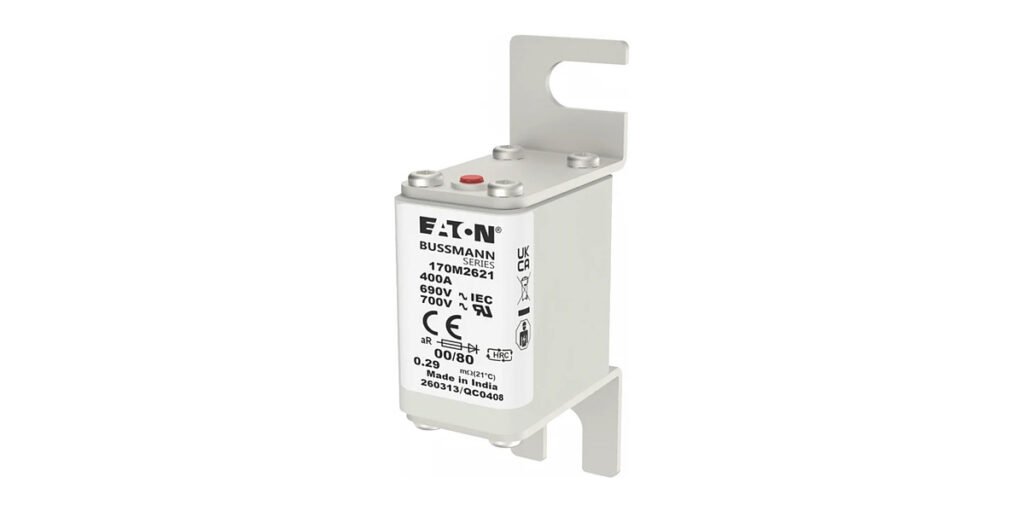
- 170M2621 is a 400 A square-body fuse used as a thyristor protection example.
- Its total-clearing I2t is 125,000 A2s at 660 V in the published example.
- 170M6198 is a 1000 A, 1250 V AC size 3 aR fuse with pre-arcing I2t of 450,000 A2s.
- 170M6198 total-clearing I2t is 2,150,000 A2s at 1000 V and 2,750,000 A2s at 1250 V.
- I2t values must be compared at the same voltage and test conditions.
- Series coordination compares downstream total-clearing I2t with upstream pre-arcing I2t.
- Parallel-path designs require current-sharing assumptions to be stated explicitly.
High-speed fuses are selected not only to carry normal operating current but also to limit the energy delivered during a fault. In semiconductor applications, the relationship between fuse let-through energy and device withstand can determine whether a fault is isolated before it causes wider equipment damage.
This guide explains the role of pre-arcing I²t and total-clearing I²t in the selection of Eaton Bussmann 170M fuses. It uses published examples from 170M2621 and 170M6198 to show why voltage conditions and exact model numbers must be preserved when comparing data.
1. What I²t means in fuse selection
I²t is the integral of current squared over time. Fuse datasheets commonly distinguish:
- Pre-arcing I²t: the energy integral up to the point at which the fuse element begins to melt and arcing starts.
- Total-clearing I²t: the energy integral over the complete interruption process, including the arcing interval, until current is cleared.
For semiconductor protection, the total-clearing value is often especially important because the protected device experiences current until interruption is complete. However, both values may be relevant to coordination with other fuses and circuit components.
Always compare values at the applicable voltage and stated test conditions. A number copied from a different voltage column may not be valid for the circuit under review.
2. Model example: 170M2621
Eaton’s high-speed fuse application guide uses Bussmann 170M2621 as an example in a thyristor-protection calculation. The example identifies the 170M2621 as a 400 A square-body fuse selected for an application, then checks the fuse’s total-clearing I²t against the protected thyristor’s withstand.
The guide gives a total-clearing I²t value of 125,000 A²s at 660 V for that fuse and illustrates an adjustment to a lower applied voltage using the manufacturer’s voltage factor. The example is useful because it demonstrates the method—not because the same value can be copied to another model or installation.
For an actual design, use the current datasheet and the device manufacturer’s withstand information. Do not treat a worked example as a universal fuse-selection recommendation.
3. Model example: 170M6198
Eaton lists 170M6198 as a 1000 A, 1250 V AC size 3 aR fuse. Its product record provides model-specific I²t values:
| Parameter | Published value |
|---|---|
| Pre-arcing I²t | 450,000 A²s |
| Total-clearing I²t at 1000 V | 2,150,000 A²s |
| Total-clearing I²t at 1250 V | 2,750,000 A²s |
| Rated current | 1000 A |
| Rated voltage | 1250 V AC |
| Interrupting rating | 100 kA |
The clearing values differ by applied voltage. This is a direct reason not to compare I²t values without their associated voltage and test conditions. The published values are specific to 170M6198; do not apply them to 170M6197, 170M6248 or any other nearby catalog number without checking that model’s own data.
4. Coordination between semiconductor and line fuses
In a rectifier with individual semiconductor fuses and an upstream line fuse, the designer may need to ensure that the device fuse clears selectively without unnecessarily opening the fuses protecting healthy parallel paths. The Eaton application guide discusses these coordination relationships and worked examples.
For a simple series coordination check, the total-clearing I²t of the downstream semiconductor fuse must be compared with the pre-arcing I²t of the upstream fuse under compatible conditions. In parallel-path designs, the current-sharing assumptions and number of parallel paths affect the analysis. Unequal current sharing and the number of devices permitted to be unavailable must also be considered.
The equations in a real protection study should follow the manufacturer’s application guide and the actual circuit topology. Do not apply a simplified formula without checking whether its assumptions match the equipment.
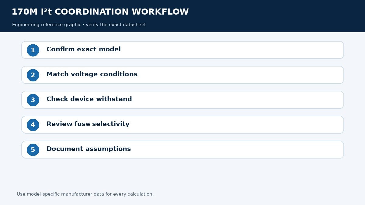
5. A practical I²t review workflow
- Identify the exact fuse catalog number and current datasheet revision.
- Confirm the system voltage and the relevant AC or DC application rating.
- Establish prospective fault current and the circuit conditions used in the manufacturer’s data.
- Obtain the protected semiconductor’s I²t or short-circuit withstand information from its manufacturer.
- Compare total-clearing I²t with the device withstand at compatible conditions.
- Check pre-arcing I²t where fuse-to-fuse selectivity or parallel-path coordination matters.
- Review peak let-through current, arc voltage and other published limits where required.
- Check ambient temperature, enclosure thermal conditions, power loss and continuous-current derating.
- Document the assumptions and obtain approval from the responsible power-electronics engineer.
6. Why nominal current is not enough
Two fuses with the same rated current may have different voltage ratings, clearing characteristics, terminal designs or indicator options. A higher-current fuse is not automatically safer for a semiconductor; it may allow more energy through during a fault. Conversely, choosing a lower-current fuse without reviewing the load and thermal conditions can create nuisance operation.
The goal is a coordinated protection system: the fuse must carry the required normal current while clearing faults within the limits of the protected components and the equipment design.
Related 170M guides
Browse all 170M high-speed fuses
Filter the full FuseStock 170M range by current, voltage and body size.
170M1802–170M1869 IGBT fuse guide
DC-rated 170M families for IGBT and inverter protection, 25 A to 500 A.
What to check beyond the ampere rating on a 1400 V AC aR fuse.
High-current 170M fuses: 170M6146–170M6249
800 A to 1100 A models, indicator options and model-specific I²t.
Find 170M models on FuseStock
Browse the FuseStock 170M collection by full catalog number. For technical review or an RFQ, include the equipment model, circuit voltage, semiconductor type and original fuse number.
Manufacturer references
- Eaton Bussmann high-speed fuse application guide
- Eaton 170M6198 product page
- Eaton 170M2621 product listing and product image
- Eaton Bussmann IEC high-speed fuse catalogue
Engineering note: I²t coordination is an engineering calculation. Confirm all values in current manufacturer documentation and obtain qualified review before changing fuse specifications.
Frequently Asked Questions
What is the difference between pre-arcing and total-clearing I2t?
Pre-arcing I2t ends when the element melts and arcing begins; total-clearing I2t runs to the completion of interruption and is the value normally compared with semiconductor withstand.
Why do the published I2t values change with voltage?
Because the clearing process depends on the applied voltage. 170M6198 is listed at 2,150,000 A2s at 1000 V but 2,750,000 A2s at 1250 V.
Can I use the 170M2621 example value for another fuse?
No. The 125,000 A2s figure at 660 V belongs to that model and condition; it demonstrates the method, not a transferable result.
How is fuse-to-fuse selectivity checked?
Compare the downstream fuse's total-clearing I2t with the upstream fuse's pre-arcing I2t under compatible conditions, as described in the manufacturer's application guide.
Is a higher current rating always safer for the semiconductor?
No. A larger fuse may let more energy through during a fault, so clearing I2t and device withstand still have to be compared.
What else affects coordination besides I2t?
Peak let-through current, arc voltage, ambient temperature, enclosure thermal conditions, power loss and continuous-current derating.