



High-Speed Semiconductor Fuses: IEC 60269-4 aR, gR, gS and DC Converter Protection
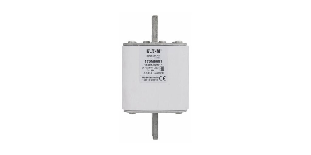
High-speed semiconductor fuses are designed to limit the current and thermal stress associated with faults in rectifiers, converters, drives, UPS systems, battery systems and other power-electronic equipment. They are characterized by low pre-arcing I²t, low total-clearing I²t, strong current limitation and controlled arc voltage.
The trade vocabulary is loose. “Semiconductor fuse,” “high-speed fuse,” “ultra-fast fuse,” “rectifier fuse,” “DC-link fuse” and, in some catalogs, “SEMICON” can refer to overlapping products. None of those names by itself defines the electrical behavior. A defensible specification uses the actual utilization category, voltage, current, breaking capacity, I²t, cut-off current, power dissipation and mechanical form.
IEC 60269-4:2024 is the key international standard for fuse-links used to protect semiconductor devices. It supplements IEC 60269-1 and applies to circuits up to 1000 Vac and 1500 Vdc, with provisions that can also be applied to higher voltages where appropriate.
aR, gR and gS: the current IEC 60269-4 categories
The source draft discusses aR and gR but misses the current standard’s third important category: gS.

Under IEC 60269-4, the first letter defines the breaking range:
- a = partial-range breaking capacity;
- g = full-range breaking capacity.
The second letter defines the semiconductor utilization class. The 2024 standard distinguishes R and S. Type R is typically faster and gives lower I²t; Type S is generally optimized for lower power dissipation and improved cable utilization.
This is more precise than describing “R” merely as “rectifier.” The 2024 standard explicitly treats R and S as semiconductor utilization classes and defines their performance emphasis.
An aR fuse is not required to interrupt every current that will eventually melt its element. It has a specified minimum breaking current and must be applied so that lower-overcurrent conditions are handled by electronic current control, another protective device or the equipment’s protection scheme.
For voltage-source inverters, there is an additional point that matters in modern DC systems: IEC 60269-4 recognizes that some aR fuse-links used for VSI protection need different DC short-circuit testing. The standard requires the manufacturer to state the relevant DC characteristics for VSI protection. Do not assume that an AC aR rating automatically establishes the required DC/VSI performance.
High-speed fuses do not “beat” an IGBT’s microsecond short-circuit timer
The biggest correction to the source draft is the IGBT protection model.

Modern IGBTs, SiC MOSFETs and similar actively switched devices can be damaged extremely quickly during a hard short circuit. Their primary protection is therefore electronic fault detection and turn-off—for example desaturation detection, gate-driver protection and converter control.
Eaton’s current high-speed fuse application guide says that an IGBT can limit current for a short period and can often be switched off before damage occurs. It also notes that converter busbar inductance is intentionally kept so low that the physical arrangement may preclude putting a fuse directly in every switch path. For power transistors, Eaton states that even high-speed fuses may not react fast enough to protect the semiconductor device itself, while still being essential to prevent case rupture and isolate the failed circuit.
Littelfuse makes the same point from a different direction in its high-power crowbar guidance: in MW-class converters, conventional fuses are generally too slow to save IGBTs or MOSFETs that can be destroyed in less than tens of microseconds, so the fault current may need to be diverted to a robust crowbar path long enough for the fuse or switchgear to clear it.
That means the source draft’s simple requirement
t_fuse < t_IGBT
is not a reliable design rule, and a statement such as “a fuse clears in 6 µs so the IGBT survives a 10 µs fault” should not be published as a general engineering method.
The fuse still matters enormously. Once an IGBT or module fails short, the available current can rise violently. A high-speed fuse can limit the resulting fault, reduce case/busbar damage and isolate the failed branch so the fault does not propagate through the converter.
Thyristors and diodes: where I²t coordination is strongest
For thyristors and power diodes, direct I²t coordination is much more established because device manufacturers commonly publish surge-current and I²t withstand data.
The engineering comparison is:
Fuse total-clearing I²t < semiconductor I²t withstand
at the relevant applied voltage and fault condition.
Eaton demonstrates this directly in its high-speed application guide. In a worked thyristor example, the fuse’s total I²t is corrected for the actual voltage and compared with the thyristor’s published I²t withstand. The fuse’s arc voltage is also checked against the device’s voltage withstand.
This produces three distinct checks:
- the fuse current rating and thermal derating must carry the normal semiconductor current;
- fuse total-clearing I²t must remain below the protected device’s applicable withstand;
- the fuse’s peak arc voltage must remain within what the protected equipment can tolerate.
Peak cut-off current can matter as well, especially where busbar, capacitor and package mechanical stress is a design limit.
DC protection depends on voltage, fault current and time constant
A DC fuse application cannot be reduced to voltage and ampere rating.
The interruption severity depends on the actual DC voltage, prospective current and the circuit L/R time constant. Eaton’s application guidance for using high-speed fuses in DC systems explicitly evaluates all three.
IEC 60269-4:2024 also reflects this. Its DC cut-off and I²t requirements use defined time constants, and it states that cut-off current changes when the actual circuit time constant differs from the test condition.
For the designer, the practical questions are:
- Is the exact fuse explicitly DC rated?
- At what DC voltage?
- At what interrupting rating?
- What circuit time constant or VSI test condition applies?
- Does the manufacturer publish the required DC pre-arcing/clearing data?
A high AC rating is not proof of DC capability. Conversely, some specialized DC high-speed fuses have very high DC ratings. Mersen’s current high-speed portfolio includes DC product families extending from hundreds of volts to several kilovolts, while Eaton offers aR traction/DC products such as 2000 Vdc square-body fuses.
There is no universal rule that a semiconductor fuse’s DC voltage rating is higher or lower than its AC rating. They are separate tested claims.
Reverse current and backfeed: analyze the circuit, not an invented “reverse I²t” fuse rating
Parallel converters, batteries, capacitors and regenerative drives can feed a fault from unexpected directions. That makes reverse or backfeed fault paths important.
But a fuse should not automatically be assigned a separate “reverse I²t withstand” or “reverse voltage rating” unless the manufacturer actually publishes such a directional characteristic. Standard fuse-links are generally applied by their rated AC/DC performance and circuit test conditions; current direction is not a substitute for the DC voltage, prospective current and time-constant analysis.
For a multi-source DC bus, calculate every source that can feed the fault—including capacitors and adjacent converter branches—and verify the fuse for the resulting current waveform and DC conditions. If the fuse is polarized or has a direction-specific DC rating, the manufacturer will state it.
I²t, cut-off current and arc voltage
I²t is a thermal-stress integral in A²s, not energy in joules by itself.
The most useful high-speed fuse parameters are:
Total-clearing I²t changes with applied voltage because the arcing interval changes. Use the manufacturer’s voltage correction data where provided rather than comparing a headline value at one voltage with a device operating at another.
Construction and regional forms
High-speed fuse performance comes from element geometry, filler, body construction and terminals. Eaton lists ceramic, fiberglass, silver, copper, brass, steel and silica sand among the materials used in its high-speed families. Mersen describes square-body Protistor products with die-cut silver elements embedded in solidified sand.
The source draft’s “North American bolted versus IEC cartridge” split is too simple. Both North American and IEC-market semiconductor fuse families are available as cylindrical, round-body, square-body, blade, flush-end, threaded and bolted forms.
Mersen’s current portfolio maps North American round and square-body products alongside IEC, DIN and British Standard styles. The mechanical system should therefore be specified by the exact product drawing and regional equipment interface rather than by assuming that North America means “bolt-down” and IEC means “cartridge.”
Likewise, there is no generic requirement that these fuses must “vent” along a prescribed path when they operate. High-speed current-limiting fuses are enclosed, sand-filled devices designed to contain and extinguish the arc. Follow the exact manufacturer’s mounting, clearance, indicator, heat-dissipation and torque instructions; do not invent a universal vent zone if the datasheet does not specify one.
Current range is much wider than “hundreds to thousands of amps”
Large square-body semiconductor fuses certainly reach several thousand amperes. Mersen currently publishes high-performance square-body aR products into the multi-kiloamp range.
But IEC 60269-4 semiconductor protection is not defined by “high current.” The same technology family also includes much smaller cylindrical and miniature products. Mersen’s current range includes semiconductor-oriented products well below 100 A, and Eaton offers cylindrical high-speed fuses such as 22×58 mm aR products.
The category is defined by its semiconductor-protection performance, not by a minimum ampere rating.
A practical selection sequence

Start with the circuit topology: rectifier, inverter DC link, VSI, battery bus, traction system or individual thyristor/diode cell.
Then determine maximum operating voltage, transient voltage, prospective fault current and DC time constant. Select only a fuse family that is explicitly rated/tested for those conditions.
Choose aR, gR or gS according to the required breaking range and system protection strategy. Do not substitute categories from the letters alone.
Apply thermal derating for ambient, enclosure and mounting. Check rated current, watts loss and holder/base thermal limits.
Then perform the actual protection check. For thyristor/diode applications this can include total-clearing I²t and arc-voltage coordination. For IGBT/SiC converters, integrate the fuse with the electronic short-circuit protection scheme and evaluate what the fuse is expected to save: the switch itself, the module package, the busbar, the DC link or the rest of the converter.
Finally, verify mounting dimensions, terminal torque, indicator/microswitch arrangement and any instruction to replace companion fuses that were exposed to the same fault current.
Official product references
For real product appearance, use manufacturer media rather than generated product images:
- IEC 60269-4:2024: https://webstore.iec.ch/en/publication/66094
- Eaton Bussmann high-speed fuse application guide: https://www.eaton.com/content/dam/eaton/products/electrical-circuit-protection/bussmann-iec-high-speed-semi-conductors-fuses/eaton-bussmann-series-high-speed-fuses-application-guide-br132015en-en-us.pdf
- Eaton 170M2041 2000 Vdc aR traction fuse: https://www.eaton.com/us/en-us/skuPage.170M2041.html
- Eaton FWP-25A22FI 22×58 mm aR high-speed fuse: https://www.eaton.com/us/en-us/skuPage.FWP-25A22FI.html
- Mersen AC & DC high-speed fuse solutions: https://www.mersen.com/sites/default/files/medias/files/2025-04/BR-MERSEN-AC-DC-FUSE-SOLUTIONS-EN.pdf
- Mersen Protistor square-body high-speed fuse range: https://us.mersen.com/en/high-speed-fuses/square-body
- Littelfuse POWR-SPEED high-speed fuse fundamentals: https://www.littelfuse.com/assetdocs/powr-speed-overcurrent-protection-fundamentals?assetguid=4b7c2998-57e4-4214-a377-e1d1722b669b
No AI-generated product photo is used in this article.
Frequently asked questions
What is the difference between aR, gR and gS?
aR is partial-range semiconductor protection. gR and gS are full-range. IEC 60269-4 describes R as typically faster/lower-I²t, while S is optimized toward lower power dissipation and improved cable utilization.
Can a high-speed fuse save an IGBT from a 10 µs hard short circuit?
Do not assume so. Modern IGBT/SiC short-circuit protection is primarily electronic. High-speed fuses remain essential for limiting secondary fault energy, preventing catastrophic package damage and isolating failed branches, but a simple “fuse clears before the 10 µs IGBT limit” rule is not reliable.
Is I²t coordination still valid for semiconductors?
Yes, especially for thyristors and diodes with published I²t withstand data. Compare the fuse total-clearing I²t at the relevant applied voltage with the device’s applicable withstand, and also check arc voltage and peak current where required.
Does an aR fuse provide overload protection?
No. It has partial-range breaking capacity. Lower-overcurrent protection must be provided by the equipment/control system or another protective function.
Is every semiconductor fuse a DC fuse?
No. IEC 60269-4 covers semiconductor fuse-links for AC and DC applications. Use the exact AC/DC rating of the product.
Do semiconductor fuses have a standard reverse I²t rating?
Not as a generic rule. If a manufacturer publishes directional or reverse characteristics, use them; otherwise analyze the backfeed fault with the fuse’s stated DC ratings and test conditions.