



Fuse I²t Explained: Melting I²t, Total Clearing I²t and Peak Let-Through

I²t is one of the most useful fuse parameters and one of the easiest to misuse. The symbol looks like energy, fuse catalogs often place it beside let-through data, and coordination studies frequently compare two I²t numbers without checking whether one is melting I²t and the other is total clearing I²t.
The first correction is conceptual: I²t is not energy by itself. It is the time integral of current squared,
I²t = ∫ i² dt
with units of ampere-squared seconds (A²s). Electrical heating in a resistive part is related to ∫i²Rdt. Fuse I²t is therefore best understood as a thermal-stress quantity that allows devices and conductors to be compared without pretending that every part in the circuit has the same resistance.
The second correction is equally important: peak let-through current and I²t are different quantities. Peak let-through is an instantaneous current value used to evaluate electromechanical stress and the peak current that reaches downstream equipment. I²t accounts for the current waveform over time and is used for thermal withstand, fuse coordination and semiconductor protection.
Melting I²t and total clearing I²t
A current-limiting fuse does not go from “intact” to “open circuit” in one instant. The element first heats and melts; then an arc exists inside the fuse until the arc is extinguished.

Melting I²t, also called pre-arcing I²t, is the integral of current squared from fault inception until the element melts. It describes the fuse element’s response before the arc phase begins.
Arcing I²t is the additional I²t passed after melting while the internal arc is being extinguished.
Total clearing I²t is the sum:
Total clearing I²t = melting I²t + arcing I²t
That relationship is explicitly shown in current Mersen and Littelfuse fuse application literature. Total clearing I²t is therefore greater than melting I²t for a given clearing event.
The size of the arcing contribution is not a universal percentage. It depends on fuse design, system voltage, prospective current, power factor or DC time constant, and other test conditions. The source draft’s fixed claims that arcing is normally 75–95% of total I²t and that ignoring it understates stress “by roughly an order of magnitude” are too broad to publish as general rules.
Voltage matters particularly to total clearing I²t because arc duration and arc energy depend on the recovery voltage the fuse must interrupt. Mersen notes that published worst-case total I²t is typically stated at the fuse’s rated test voltage; when the applied voltage is lower, total clearing I²t can also be lower. Always use data at conditions applicable to the installation.
How to read a peak let-through chart
Peak let-through charts are where RMS-versus-peak mistakes usually start.

On a typical current-limiting fuse chart:
- the horizontal axis is the prospective or available short-circuit current in RMS symmetrical amperes;
- the vertical axis is the instantaneous peak let-through current, usually written Ip.
Mersen states this directly in its current-limitation guidance: the X axis is available fault current in RMS symmetrical amperes, while the Y axis is instantaneous peak let-through current.
That means the common instruction “read the datasheet let-through value as RMS and multiply by 2.3” is wrong for this type of chart. If the Y axis already says peak let-through, it is already the peak value.
The familiar 2.3 line has a different purpose. In many North American fuse let-through charts, a diagonal reference line represents a conservative maximum available first-peak current for an unfused circuit relative to the RMS symmetrical prospective current. Mersen explains that the possible first peak depends on circuit asymmetry and X/R; 2.3 is used as a practical high-value reference in its charts. It is not a universal conversion factor to apply blindly to every let-through number.
A correct reading therefore looks like this:
- Determine the available short-circuit current at the fuse location in RMS symmetrical amperes.
- Enter the chart on the horizontal axis.
- Move to the curve for the selected fuse rating.
- Read the vertical axis as peak let-through current.
- Compare that peak value with the downstream equipment’s applicable peak withstand or with the manufacturer’s protection data.
Always read the axis labels. Some data tables use different conventions, and the quantity printed by the manufacturer governs.
Using I²t for component protection and fuse selectivity
For downstream component protection, the basic concept is straightforward: the fuse should clear before the protected component exceeds its thermal withstand.
A common high-fault-current check is:
Fuse total clearing I²t < protected component I²t withstand
Mersen specifically describes fuse clearing I²t as a quantity that can be compared with published I²t withstand values for components such as semiconductor devices and cables.
For selectivity between two current-limiting fuses, the asymmetry between the two I²t quantities matters. The downstream fuse must finish clearing before the upstream fuse reaches its melting condition. At high fault currents, that leads to the comparison:
Downstream total clearing I²t < upstream minimum melting I²t
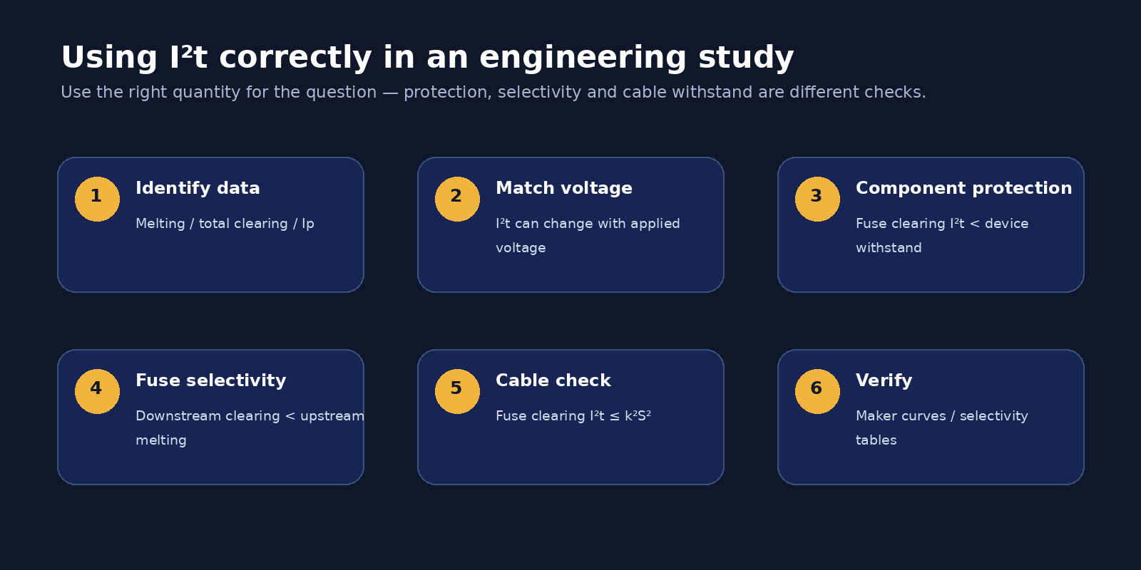
That is a valid high-fault-current coordination principle, and Mersen explicitly uses it when explaining fuse selectivity. What should not be added is a generic safety multiplier such as 1.6, 2 or 10 and then presented as an industry-wide standard. The source draft’s “K = 1.6 or 2” and universal “10 I²t rule” are not supported as general fuse standards by the manufacturer material reviewed here.
In practical work, use the manufacturer’s selectivity ratio tables or coordination software whenever they are available. Those tables incorporate the tested time-current and high-fault-current behavior of the actual fuse families. For combinations near the limit, the manufacturer’s coordination data is more defensible than inventing a universal I²t margin.
Time-current curves still matter. I²t comparison is most useful in the high-current region where fuse clearing occurs within a fraction of a cycle and ordinary TCC plots may no longer provide enough discrimination detail. Selectivity over the complete overcurrent range requires both the low-current time-current behavior and the high-current current-limiting behavior.
Cable short-circuit withstand
The source draft’s cable equation needs an important correction.
For short-duration adiabatic short-circuit heating, IEC practice commonly uses:
I²t ≤ k²S²
where:
- I is the RMS short-circuit current through the conductor;
- t is the fault duration;
- S is conductor cross-sectional area in mm²;
- k is the conductor/insulation constant based on material and permitted initial/final temperatures.
Equivalently:
S ≥ √(I²t) / k
There is no additional generic a_c denominator in the IEC adiabatic relationship. Schneider Electric’s IEC-based Electrical Installation Guide states the short-circuit thermal relationship as I²t = k²S² for the applicable short-duration range.
When a current-limiting fuse protects the cable, compare the fuse’s total clearing I²t at the relevant fault conditions with the cable’s permissible k²S². If the fuse lets through less I²t than the cable can withstand, the thermal short-circuit check is satisfied, subject to the assumptions and limits of the adiabatic method.
Do not use one headline I²t value without checking voltage and the manufacturer’s conditions. Total clearing I²t can change with applied voltage and fault current.
Semiconductor protection: both I²t and peak current matter
High-speed semiconductor fuses exist because power semiconductors have far less short-circuit thermal margin than motors, cables and transformers. Their fuse elements are designed to produce low melting and clearing I²t and strong current limitation.
It is too absolute, however, to say that a general-purpose fuse can never protect a semiconductor under any circumstance. The engineering question is whether the protective device’s let-through and clearing characteristics are below the semiconductor manufacturer’s damage limits for the specific fault. In most dedicated power-electronics protection applications, that requirement leads to an aR/gR or other high-speed fuse.
It is also incorrect to say that semiconductor protection is “overwhelmingly peak current rather than energy.” Both quantities can matter. Semiconductor manufacturers and high-speed fuse manufacturers commonly publish I²t coordination guidance, and Mersen explicitly states that a fuse’s clearing I²t should be below the semiconductor device’s I²t withstand. Peak let-through is separately important for electrodynamic and instantaneous current stress.
The right workflow is therefore to compare the fuse manufacturer’s high-speed fuse data with the semiconductor manufacturer’s short-circuit/overload limits, including any required correction factors for voltage, temperature and repetitive duty.
Common mistakes
The most damaging mistakes are usually unit and definition mistakes rather than arithmetic errors.
Do not compare upstream total clearing I²t with downstream melting I²t for fuse selectivity; that reverses the engineering question. Do not assume a let-through chart’s vertical axis is RMS. Do not multiply a peak let-through value by 2.3 a second time. Do not treat I²t as joules without the resistance term. Do not use one generic I²t value at a different voltage from the actual installation. And do not replace manufacturer selectivity tables with a universal ratio that the manufacturer has not published.
A final caution concerns temperature and pre-loading. Fuse operating characteristics are thermal, so ambient temperature, enclosure heating and pre-load can change the time to melt. Manufacturer derating data and application notes should be used when coordination margins are tight.
Official technical references
This article is based on manufacturer and IEC-oriented engineering references rather than invented representative I²t tables:
- Mersen semiconductor fuse applications guide: https://www.mersen.com/sites/default/files/files_imported_ep/BR-Semiconductor-Fuse-Applications-Guide-Brochure.pdf
- Mersen current limitation / let-through guidance: https://www.mersen.com/en/resources/welcome-arc-flash-info-center/reducing-arc-energies-fuses
- Mersen selectivity application information: https://us.mersen.com/document-center/ap-application-information
- Eaton Bussmann Fuseology: https://www.eaton.com/content/dam/eaton/support/austria/downloads/Handbuch_Fuseology_Overcurrent_protection.pdf
- Littelfuse Fuseology selection guide: https://m.littelfuse.com/~/media/electronics/product_catalogs/littelfuse_fuseology_selection_guide.pdf%20.pdf
- IEC-based cable withstand guidance: https://www.electrical-installation.org/enwiki/Verification_of_the_withstand_capabilities_of_cables_under_short-circuit_conditions
No AI-generated product photo is used in this article.
Frequently asked questions
Is I²t the same as energy?
No. I²t has units of A²s. Actual resistive heating energy involves ∫i²Rdt. I²t is used as a thermal-stress measure because it allows useful comparisons between a fuse and a device or conductor withstand.
What is the difference between melting and total clearing I²t?
Melting or pre-arcing I²t covers the current-squared integral up to the instant the element melts. Total clearing I²t includes both melting and the subsequent arcing interval until current is interrupted.
Is peak let-through current RMS?
On the common current-limiting fuse charts described by Mersen, no. The horizontal axis is prospective RMS symmetrical current and the vertical axis is instantaneous peak let-through current. Always read the chart labels.
Should I multiply let-through current by 2.3?
Only if the manufacturer has given you an RMS symmetrical current and you specifically need the applicable peak reference. Do not apply 2.3 to a value already labeled peak let-through.
How do I check fuse-to-fuse selectivity at high fault current?
A key high-current condition is that the downstream fuse’s total clearing I²t be below the upstream fuse’s minimum melting I²t. For an actual design, use the manufacturer’s selectivity ratio table or coordination tool for the exact fuse families.
What equation should I use for cable short-circuit thermal withstand?
For the usual short-duration adiabatic IEC check, I²t ≤ k²S², or S ≥ √(I²t)/k.