



Bussmann Low-Peak Series: Illustrated Technical Comparison Guide

Eaton Bussmann Low-Peak® Series
Technical Comparison Guide
Which Low-Peak fuse should you choose?
Start with the electrical duty and mounting system. A headline 300 kA rating does not cover every fuse, amperage or application.
LP-CC
Small control and motor circuits
0.5–30 A · 200 kA AC. Very compact ferrule design for appropriately rated Class CC holders.
TCF
High-density finger-safe panel systems
1–400 A · 300 kA AC only within specified lower ratings. Dedicated CUBEFuse holder ecosystem.
LPJ
Industrial feeders and machine panels
1–600 A · 300 kA AC across the series, with different body and terminal types by rating.
LPS-RK
Class R replacements and upgrades
0.1–600 A · 300 kA AC. Useful for retrofits with compatible Class R installations.
Read First — the 300 kA Claim Does Not Apply Across All Ampere Ranges
Eaton describes the Low-Peak™ family as “the industry’s only UL® Listed and CSA® Certified fuses with a 300 kA interrupting rating.” That statement carries explicit qualifiers, and actual interrupting capability varies by ampere rating within each series. Misapplying the figure leads to incorrect selection.
| Series | Class | IR @ 600 Vac | IR @ 300 Vdc | Ampere Range | Note |
|---|---|---|---|---|---|
| LP-CC | CC | 200 kA | 20 kA (AIR) | 1/2 – 30 A | 200 kA throughout — 300 kA claim not applicable |
| TCF | CF | 300 kA (≤100 A) 200 kA (110–400 A) |
100 kA | 1 – 400 A | Stepped rating — re-verify above 100 A |
| LPJ | J | 300 kA (all ratings) | 100 kA | 1 – 600 A | Consistent across the full range |
| LPS-RK | RK1 | 300 kA (all ratings) | 100 kA | 1/10 – 600 A | LPN-RK (250 V) also rated 300 kA |
The footnote to Eaton’s “50% higher interrupting rating” statement in Product Profile PP 10119 reads:
“* 50% higher IR (300kA) than any other UL and CSA Listed Fuse. Includes Class J, L and R fuses.“
Class CC and the higher-current portion of Class CF fall outside this scope. Do not specify 300 kA for those ratings in quotations or technical submissions.
LOW-PEAK® covers Class CC, CF, J, L and RK1 — it does not include Class RK5. RK5 belongs to FUSETRON® (200 kA); Class R fast-acting types belong to LIMITRON® (200 kA). Confirm the brand tier before comparing ratings across series.
Core Electrical Ratings
Identify the physical formats
Real catalog photographs · not to scale · source credits below each photo
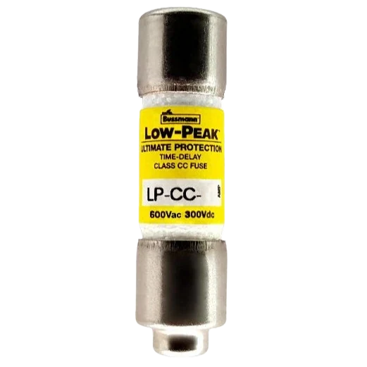


Photos are product recognition aids, not dimension drawings. They are loaded from their original websites when you are online. Rights remain with the respective owners.
| Parameter | LP-CC | TCF | LPJ | LPS-RK |
|---|---|---|---|---|
| Class | CC | CF | J | RK1 |
| Rated voltage | 600 Vac 300 / 150 Vdc* |
600 Vac 300 Vdc |
600 Vac 300 Vdc |
600 Vac (LPS-RK) 250 Vac (LPN-RK) |
| DC voltage split | 300 Vdc: 1/2–2-8/10 A, 20–30 A 150 Vdc: 3–15 A |
300 Vdc (full range) | 300 Vdc (full range) | 300 Vdc (LPS-RK) 125 / 250 Vdc (LPN-RK) |
| Ampere range | 1/2 – 30 A | 1 – 400 A 6–400 A indicating |
1 – 600 A | 1/10 – 600 A |
| AC interrupting rating | 200 kA | 300 kA / 200 kA | 300 kA | 300 kA |
| DC interrupting rating | 20 kA (AIR) | 100 kA | 100 kA | 100 kA |
| Time-delay | 200% / 12 s different basis |
500% / 10 s | 500% / 10 s | 500% / 10 s 8 s for 0–30 A |
| Construction | Dual-element | Dual-element | Dual-element | Dual-element |
| Tube material | Melamine | Glass-filled PES | Glass | Glass |
| Indicating version | None | Yes — TCF_ (easyID™) | Yes — LPJ-__SPI (easyID™) | Yes — LPS-RK-__SPI |
| Operating temperature | Not stated | −40 – +80 °C | Not stated | Not stated |
| Data sheet | 1023 | 9000 | 1006 / 1007 1063 (SPI) |
1001 / 1002 1003 / 1004 |
* LP-CC DC voltage is split by ampere rating; ratings must not be interchanged.
Certification & Compliance References
| Agency | LP-CC | TCF | LPJ | LPS-RK |
|---|---|---|---|---|
| UL standard | UL 248-4 | UL 248-17 | UL 248-8 | UL 248-12 |
| UL Guide / File | JDDZ / E4273 | JDDZ / E4273 | JDDZ / E4273 SPI: JFHR / E56412 |
JDDZ / E4273 |
| CSA standard | C22.2 No. 248.4 | C22.2 No. 248.17 | C22.2 No. 248.8 | C22.2 No. 248.12 |
| CSA Class / File | 1422-02 / 53787 | 1422-02 / 53787 | 1422-02 / 53787 | 1422-02 / 53787 |
| CE marking | Yes (EU LVD 93-68-EEC2000) | Yes ≤100 A only | Yes | Yes |
| RoHS | Check SKU declaration | Check SKU declaration | Check SKU declaration | Check SKU declaration |
| IEC product certification | Request evidence if required | Request evidence if required | Request evidence if required | Request evidence if required |
- Common baseline across all four series: UL Guide JDDZ / File E4273, CSA Class 1422-02 / File 53787. This combination satisfies typical compliance documentation.
- Legacy versions differ: 2004-era Cooper Bussmann data sheets used Guide JFHR / File E56412. Current Eaton versions standardise on JDDZ.E4273 — always cite the current version.
- CE marking is not an IEC product certificate. Do not infer IEC standard certification from a CE mark or UL/CSA listing. Request exact SKU-specific conformity evidence if an IEC certificate is a project requirement.
- Indicating versions differ: LPJ-SPI and certain TCF indicating ratings fall under UL Special Purpose (JFHR / E56412). They still meet UL 248-8 performance requirements, but the category must be stated in submissions.
Current Limitation & Downstream SCCR Propagation
Current limiting is the fuse’s decisive advantage over a circuit breaker
A current-limiting fuse does not reduce prospective fault current at its installation point, but can reduce actual let-through peak and energy. Under UL 508A Supplement SB, a panel SCCR must be determined using the prescribed component and protection methods. A high fuse interrupting rating does not automatically raise every downstream component or assembly SCCR. Record the applicable method and ratings of the specific combination.
Let-through comparison at the 30 A rating
| Series | Prospective fault | Let-through (RMS sym.) | Limiting ratio | Source |
|---|---|---|---|---|
| LP-CC-30 | 200 kA | 1,600 A | 125× | Data sheet 1023 |
| TCF30 | 200 kA | Class J electrical performance | Best | Data sheet 9000 |
| LPJ-30 | 200 kA | 3,000 A | 67× | Data sheet 1006 |
| LPS-RK-30 | 200 kA | 3,000 A | 67× | Data sheet 1001 |
Published let-through values can represent apparent RMS symmetrical or peak let-through, depending on the chart. Avoid a universal multiplier: for design and SCCR studies, use the manufacturer curve corresponding to the exact fuse, prospective fault current and output quantity.
Per UL 248, Class CC, J, T, R and L fuses can propagate a 200 kA SCCR to downstream equipment within their published let-through (I²t and Ip) limits. Class H and supplementary fuses do not carry this qualification.
Dual-Element Technology
“Dual-element” is a structural fact, not a marketing label: the overload element and short-circuit element are physically separate and connected in series, each performing a distinct task. This is the technical basis for combining time-delay with current limitation while still allowing close sizing to the load.
Two operating paths
- Persistent overload (slow path): heat accumulates until the calibrated fusing alloy reaches its rated temperature and fractures; the trigger spring releases the connector, pushing it clear of the short-circuit element and opening the circuit. This is the path that tolerates motor starting inrush.
- Short-circuit fault (fast path): the restricted sections of the short-circuit element contain minimal metal and vaporise almost instantly, forming multiple small arc-lets that burn back the element; the quartz sand filler absorbs thermal energy, fuses, and forms an insulating barrier called folgurite, forcing current to zero.
When a fault current falls within a fuse’s current-limiting range, it is not possible for the full available fault current to flow through the fuse. This is a matter of physics rather than an active interruption action. Modern current-limiting fuses complete current limiting and arc extinction within a few milliseconds — typically less than half a cycle — so the fault current never reaches its first peak.
Sizing advantage
Bussmann’s technical position: single-element non-time-delay fuses must be oversized to pass inrush currents without nuisance opening. Dual-element time-delay fuses can be sized close to full-load amps, maximising overcurrent protection.
Ambient temperature derating
The temperature derating curve of Bussmann dual-element fuses closely parallels the derating curve of motors in elevated ambient conditions. Where a motor is derated 10% in a high-temperature environment, the fuse derates by a corresponding amount — both sides match without separate correction. In hot process environments this removes a manual adjustment step from overall coordination.
Type 2 “No Damage” Coordination & Downtime Cost
To publish a Type 2 rating, the manufacturer must complete a full test programme on each contactor + overload relay + short-circuit protective device combination. The Type 2 rating is bound to that specific combination — substituting a different brand, model, or relay setting invalidates it even at the same ampere rating.
Acceptance criteria
| Criterion | Type 1 | Type 2 “No Damage” |
|---|---|---|
| Contactor contacts | Welding and complete disintegration acceptable | Light welding only, and contacts must be easily separable |
| Overload relay | Damage permitted | No damage; trip characteristics must be verified |
| Contactor housing | Deformation permitted; door must still open | No cracking or breakage impairing live-part mounting integrity |
| Terminals and conductors | Must not separate from terminals | No damage |
| Post-fault usability | Repair/replacement may be needed | Must meet applicable tested criteria |
| Dielectric test | — | 2× rated voltage, minimum 1000 V |
| Typical downtime | Depends on equipment damage | May be reduced; not guaranteed |
| Initial hardware cost | Lower | Higher (current-limiting device premium) |
| Total cost of ownership | Higher in critical processes | Lower in critical processes |
Required test sequence
| Test | What it verifies |
|---|---|
| Low-level fault (O) | SCPD operates in its time-delay region; confirms moderate fault currents do not exceed contactor let-through limits |
| High-level short-circuit (r) | Typically 100 kA with the SCPD operating in its instantaneous region; verifies contactor and overload relay integrity |
| Overload relay calibration | Trip current and trip time measured at 1.05×, 1.2× and 1.5× of setting before and after; drift beyond tolerance fails |
| Dielectric withstand | High-potential test between live parts, live parts and earth, and across open contacts |
| Discrimination test | Verifies coordination between the overload relay and the fuse |
Measured data from Mersen: a 100 A Class J fuse passes only 0.05% of the one-cycle I²t energy. Class J and Class RK1 are explicitly identified as the most suitable devices for achieving Type 2, since they complete current limitation and arc extinction in less than half a cycle and prevent the fault current from reaching its first peak.
Standard MCCBs typically cannot achieve Type 2. Certain tested current-limiting MCCBs (such as Schneider NSX Micrologic or ABB Tmax XT with LSI) qualify, and their ratings are conditional on the specific breaker series and trip unit.
Reading a Type 2 rating
Three pieces of information are always required, without exception:
Example: “Type 2 at 100 kA, 415 V, with fuse 250 A” indicates that this exact combination passed the complete test sequence above, and the rating holds only at or below that prospective fault current.
Mechanical Features & Rejection Design
| Item | LP-CC | TCF | LPJ | LPS-RK |
|---|---|---|---|---|
| Size at 30 A | 13/32″ × 1-1/2″ 10 × 38 mm — smallest |
1.88″ × 0.75″ × 1″ | 0.81″ × 2.25″ | 0.81″ × 5.0″ |
| Size at 60 A | — | — | 1.06″ × 2.38″ | 1.06″ × 5.5″ |
| Size at 200 A | — | — | 1.63″ × 5.75″ | 9.63″ × 1.61″ |
| Size at 600 A | — | — | 2.5″ × 8.00″ | 13.38″ × 2.88″ |
| Connection | Ferrule × Ferrule | Blade end | Ferrule (≤60 A) Blade (≥70 A) |
Ferrule (≤60 A) Blade (≥70 A) |
| Finger-safe | No | Yes shrouds required >110 A |
No | No |
| Bolt-in version | N/A | N/A | None | None |
Dimensional rejection
From Bussmann Class J data sheets:
Class CC and Class J share no common physical dimensions, so cross-class substitution is structurally impossible. This shifts the risk of selection error from depending on personnel training to depending on physical geometry — a material compliance benefit in facilities with high maintenance turnover.
Fuse reducers
| Series | Reducer series | Coverage |
|---|---|---|
| LPJ (Class J) | J-63, J-13, J-16, J-26, J-21, J-41, J-42, J-62, J-64 | 60 A→30 A through 600 A→400 A; most marked “not for bolt-in” |
| LPS-RK (Class R) | NO.663-R, NO.216-R, NO.616-R, NO.626-R, NO.2621-R, NO.2641-R, NO.642-R, NO.2661-R, NO.2662-R, NO.2664-R | 60 A→30 A through 600 A→400 A |
- Minimum operating voltage ≥ 75 Vac — the indication mechanism is driven by force generated by current; below this voltage it does not actuate
- Not Vdc rated — data sheets state explicitly “not Vdc rated”. In DC systems (battery, energy storage, photovoltaic, EV charging) an indicating version creates a blind spot: the fuse may be open with no visual indication
Recommended handling: for DC applications, specify a non-indicating version with upstream disconnect status monitoring, or state the limitation explicitly in the specification.
Power Loss, Thermal Performance & Operating Reliability
Watts loss at rated current
A fuse dissipates power continuously at rated current, converting it to heat. In an enclosed panelboard, cumulative heat from multiple fuses raises the internal ambient temperature, accelerating ageing of conductors, insulation and electronic components. Power loss data is therefore a key feasibility metric for high-density applications.
| Series | Power loss data availability | Note |
|---|---|---|
| TCF (Class CF) | Fully published see below |
Data sheet 9000 provides rated power loss at six current levels — a series with an accessible published table |
| LPJ (Class J) | Not published | Current-limitation curves provided; no watts loss table |
| LPS-RK (Class RK1) | Not published | Qualitative “low watt loss” statement; no numeric table |
| LP-CC (Class CC) | Not published | Melamine tube; no published power loss data for this series |
| TCF current (A) | 30 | 60 | 100 | 200 | 225 | 400 |
|---|---|---|---|---|---|---|
| Power loss (W) | 3.99 | 6.23 | 9.51 | 18.6 | 17.6 | 35.2 |
Source: Eaton Bussmann Data sheet 9000 — UL Class CF CUBEFuse.
Worked example: a 400 A three-phase circuit with three TCF400 fuses dissipates 35.2 W per phase, or approximately 105.6 W total at rated load. This heat must be removed by ventilation or enclosure thermal design. A 12-circuit panel fully populated generates over 1.2 kW of additional heat from fuses alone. High-density applications should include fuse power loss in the enclosure thermal calculation, not assess enclosure loading from load capacity alone.
Operating and storage temperature
| Series | Temperature range | Status |
|---|---|---|
| TCF (Class CF) | −40 °C to +80 °C −40 °F to 176 °F |
Stated in Data sheet 9000 |
| LP-CC / LPJ / LPS-RK | Not stated in current data sheets | Must be requested from the factory |
Caution: for high- or low-temperature projects involving LP-CC, LPJ or LPS-RK, obtain the body temperature limits from Eaton. The Class CF −40 – +80 °C range must not be assumed for the other series.
Finger-Safe Design & UL 508A Panel Compliance

Evaluate the complete holder system
Touch protection, size, amp-rating rejection and maintenance depend on the selected fuse and compatible holder or disconnect assembly. Validate the combination using current manufacturer instructions.
The Class CF CUBEFuse™ works with dedicated finger-safe holders. Other fuse types may also offer touch protection when installed with approved covers and holders. This is not solely a handling-safety feature — it determines whether a panel can be made compliant and how densely it can be populated.
UL 508A wiring requirements address the need to prevent contact with live parts. Hand accessibility directly determines:
- whether branch fuses may be positioned near the panel door without a barrier
- the achievable packing density of fuse holders
- whether the assembly passes AHJ inspection
Measured benefit: a Class CF fuse with its TCFH_N holder or CCP2 disconnect switch requires up to 70% less space than Class CC / J / RK solutions. CCP2 requires up to 69% less space than a Class J disconnect solution. The space advantage originates from installation density, not from the fuse body alone.
Footnote from Eaton Data sheet 9000:
“* Finger-safe status depends on final, installed application, and will require using accessory shrouds for 110 to 400 A ratings.”
That is: finger-safe status for 110 A and above requires accessory shrouds to be fitted. Any quotation or technical proposal covering CUBEFuse above 100 A must include these shrouds, otherwise a compliance gap results.
Safety features across the family
| Feature | LP-CC | TCF | LPJ | LPS-RK |
|---|---|---|---|---|
| Finger-safe | No | Yes shrouds >110 A |
No | No |
| Dimensional rejection | Yes | Yes | Yes | Yes |
| Amp-rating rejection on holders | Partial | Yes 30/60/100/200/225/400 A |
Partial | Partial (CR holders) |
| Insulated end caps | N/A | Yes (increases clearance to adjacent poles) | Yes (70–600 A) | Yes (70–600 A) |
| Companion disconnect | CFD30CC | CCP2 (UL 98) + NEMA 1/3R/4/4X/12 |
— | — |
Amp-rating rejection on CUBEFuse holders
This is an advanced safeguard against misapplication. Per Data sheet 9000 and the TCF90RN technical data:
- 30, 60 and 100 A holders and switches accept any CUBEFuse not exceeding their rating
- 200 A switches, and 200, 225 and 400 A holders, accept only CUBEFuse ratings of 110 A and above within their rating
This converts the common field error of fitting a smaller fuse into a larger holder from a manual check into a physical impossibility. Combined with dimensional rejection, it provides two independent layers of protection.
Inventory Simplification & Standards Compliance
Low-Peak Upgrade Program — inventory reduced by up to 33%
This figure originates from Eaton’s official Low-Peak Upgrade Program and is not an independent estimate — it follows from a defined replacement logic: a single Low-Peak fuse can replace the General Purpose, Limitron and Fusetron types that would otherwise need to be stocked separately for different applications.
| Protection tier | Family | Positioning | Interrupting rating |
|---|---|---|---|
| Ultimate Protection | LOW-PEAK® yellow label |
Dual-element construction combining fast short-circuit protection, current limitation and time-delay in a single device | Up to 300 kA |
| Advanced Protection | FUSETRON® (green label) LIMITRON® (black label) |
Fusetron: Class RK5, energy efficient, best-in-class time-delay Limitron: Class R fast-acting, approximately 10× better current limitation |
200 kA |
| Basic Protection | General Purpose (grey label) | Single-element overcurrent protection for service, feeder and branch circuits | Up to 100 kA |
Source: Eaton Fuses Made Simple™ Product Brochure 10092. Low-voltage fuses are organised into three protection tiers and four brand families, each family distinguished by a colour label.
Eaton states that “existing fuse inventory can be reduced by up to 33%“. This applies specifically where an organisation previously stocked multiple SKUs across the General Purpose, Limitron and Fusetron brands.
Correct usage: 33% is an upper bound, applicable only to organisations stocking across all three brands. An operation already using a single brand will realise substantially less. State this precondition in any proposal, so the claim is not challenged after measurement.
Arc flash hazard mitigation
Eaton lists “superior current-limitation helps reduce arc flash hazards” as the primary safety benefit of the Low-Peak family, citing three standards frameworks:
The technical chain is: fuse current limitation → reduced incident energy during a fault → lower arc flash incident energy → supports compliance with the relevant requirements. This is one compliance pathway; it does not by itself constitute “compliance with OSHA / NFPA / IEEE” — that still requires verification against actual installation conditions.
| Compliance item | Governing standard | Relationship to this product family |
|---|---|---|
| Interrupting rating adequacy | NEC 110.9 / CSA C22.1 | IR must be ≥ available fault current; LP-CC is 200 kA, others up to 300 kA |
| SCCR withstand | NEC 110.10 | Requires current-limiting characteristics so downstream component SCCR can be established |
| Fault current marking | NEC 110.24 / 110.22 | Service equipment must be field-marked with maximum available fault current |
| Motor controller coordination | IEC 60947-4-1 / UL 508E | Type 2 “No Damage”; must be confirmed per specific device combination |
| Industrial control panel | UL 508A Supplement SB | Assembly SCCR = lower of weakest unprotected component and upstream IR |
| Arc flash protection | NFPA 70E / IEEE 1584 | Current limitation reduces incident energy as one condition for compliance |
Application-Based Selection Guide
High-density panelboards & data centre PDU
Recommended: TCF (Class CF)
The only finger-safe option, with the smallest installed footprint (up to 70% space reduction with its dedicated holder) and a 300 kA rating up to 100 A — enabling a higher panel SCCR and greater design latitude on downstream equipment.
High-current feeders & transformer incomers
Recommended: LPJ (Class J)
Consistent 300 kA across the full 1–600 A range with no stepped-rating pitfalls. The most complete reducer family (J-13 through J-64) suits retrofit work. easyID™ indicating versions available.
Legacy RK holder replacement
Recommended: LPS-RK (Class RK1)
300 kA throughout (1/10–600 A) with the lowest ampere start (1/10 A) and a full range of Class R reducers, offering the best compatibility for retrofit projects.
Control circuits & small-horsepower motors
Recommended: LP-CC (Class CC)
Smallest body (13/32″ × 1-1/2″); 200 kA already satisfies NEC 110.9 for present-day high-capacity systems. Non-indicating version; verify price for the chosen SKU.
Motor control centres (MCC)
Recommended: LPJ or LPS-RK
Class J and Class RK1 are explicitly identified as the most suitable devices for Type 2 “No Damage” coordination. When properly sized, they provide Type 2 protection for NEMA and IEC motor controllers, so contactors and overload relays need not be replaced after a fault.
DC, ESS & photovoltaic systems
Recommended: LPJ / LPS-RK / TCF
All three carry 300 Vdc with a 100 kA DC interrupting rating. LP-CC DC ratings are split by ampere rating, with some ranges limited to 150 Vdc.
Features common to all four series
| Feature | Technical basis |
|---|---|
| 2:1 selective coordination ratio | A consistent amp ratio across the Low-Peak family; sizing upstream and downstream on a 2:1 basis can support coordination where confirmed by manufacturer tables, so a fault clears only the fuse nearest the fault location |
| Motor sizing (code-dependent) | Time-delay permits Motor sizing (code-dependent) for back-up motor protection, without oversizing to survive inrush |
| Type 2 “No Damage” | Properly sized, provides Type 2 coordination for NEMA and IEC motor controllers, reducing downtime |
| Arc flash hazard reduction | Superior current limitation reduces incident energy, supporting compliance with OSHA, NFPA and IEEE requirements |
| Inventory simplification | One Low-Peak fuse can replace multiple fuse types across applications; upgrading can reduce existing inventory by up to 33% |
| QuikShip availability | Most common ratings are in stock and ship within 24 hours |
Engineering Cautions
Current data sheets for LP-CC (1023), TCF (9000), LPJ (1006 / 1007) and LPS-RK (1001–1004) provide let-through tables and current-limitation curves only. Melting I²t and clearing I²t numeric tables are not published.
Where a project or specification explicitly requires I²t values, use the Eaton Fault Current Calculator or request engineering data from the factory. This reflects the current state of the official documentation, not a data gap.
| Caution | Detail |
|---|---|
| Peak conversion | Published let-through is RMS symmetrical; convert to peak using Ip = IRMS × 2.3 before comparing against equipment SCCR |
| Curve types | Published curves distinguish minimum melt, average melt and total clear. Detailed selectivity analysis must use total clear; mixing average melt values leads to misjudgement |
| DC rating limits | Indicating versions (SPI / TCF_) carry no Vdc rating; LP-CC splits 300 Vdc and 150 Vdc by ampere range and the two must not be interchanged |
| Reducer suitability | Most Class J reducers are marked “not for bolt-in”; confirm the mounting method before selection |
| Clearance at high current | Ratings above 400 A in Class J and RK1 use insulated end caps allowing mounting on CR holders, but confirm clearance to adjacent poles |
| CE scope | The CE marking for TCF covers ≤100 A only; do not reference CE above that range |
| Accessory pairing | Fuses and their specified holders and disconnect switches form a certified assembly. Verify against the manufacturer accessory list — holders and fuses of different classes must not be mixed |
This is a family-level selection guide. Before quoting or installing a fuse, verify the exact catalog number and its voltage, AC/DC interrupting rating, holder, physical clearance, SCCR treatment, time-current curves and applicable approvals. The photos and illustrative panels are not an engineering substitute for the manufacturer data sheet.